ویسکر چیست وچگونه و چرا بوجود می آید
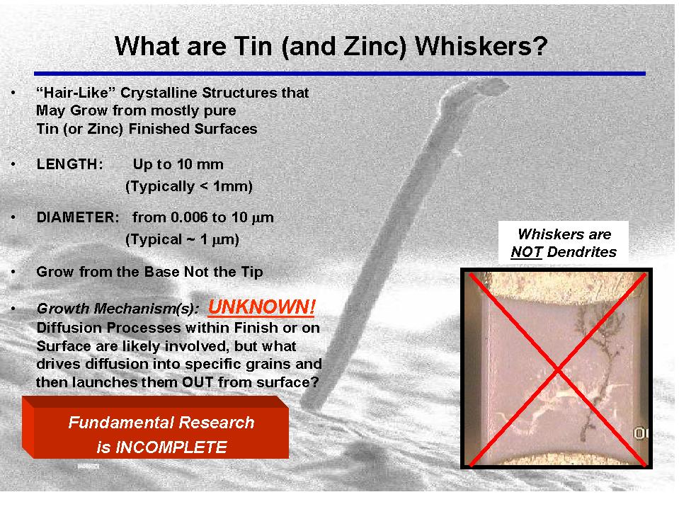
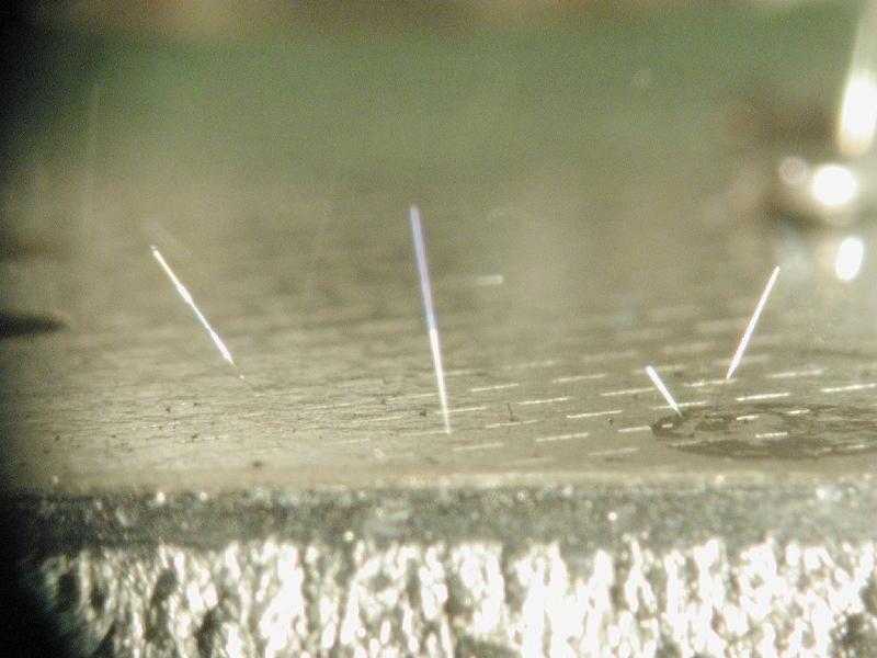
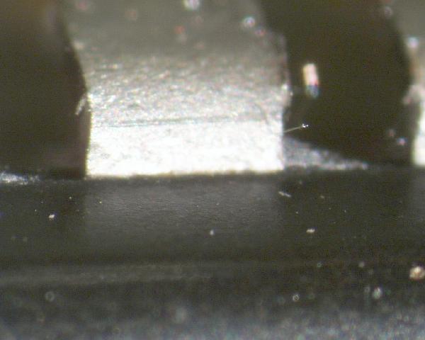
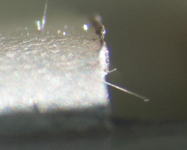
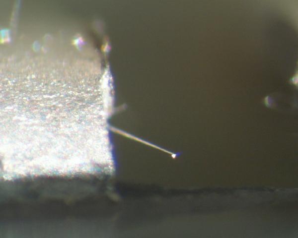
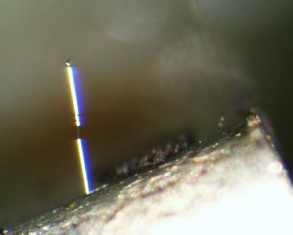
What are Tin Whiskers :Tin whiskers are electrically conductive, crystalline structures of tin that sometimes grow from surfaces where tin (especially electroplated tin) is used as a final finish. Tin whiskers have been observed to grow to lengths of several millimeters (mm) and in rare instances to lengths up to 10 mm. Numerous electronic system failures have been attributed to short circuits caused by tin whiskers that bridge closely-spaced circuit elements maintained at different electrical potentials.
Tin whiskers are not a new phenomenon. Indeed, the first published reports of tin whiskers date back to the 1940s and 1950s. Tin is only one of several metals that is known to be capable of growing whiskers. Other examples of metals that may form whiskers include Zinc, Cadmium, Indium and Antimony.
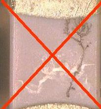
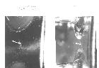
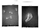
People sometimes confuse the term "whiskers" with a more familiar phenomenon known as "dendrites". Therefore, it is important to note here that whiskers and dendrites are two very different phenomena. A "Whisker" generally has the shape of a very thin, single filament or hair-like protrusion that emerges outward (z-axis) from a surface. "Dendrites", on the other hand, form in fern-like or snowflake-like patterns growing along a surface (x-y plane) rather than outward from it. The growth mechanism for dendrites is well-understood and requires some type of moisture capable of dissolving the metal (e.g., tin) into a solution of metal ions which are then redistributed by electromigration in the presence of an electromagnetic field. While the precise mechanism for whisker formation remains unknown, it is known that whisker formation does NOT require either dissolution of the metal NOR the presence of electromagnetic field.
|
|
"Dendrites" are NOT "Whiskers" |
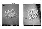
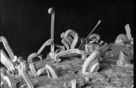
More Examples of Metal Whiskers on EEE Parts and Associated Hardware
![]()
What are the Mechanisms by which Tin Whiskers Form?
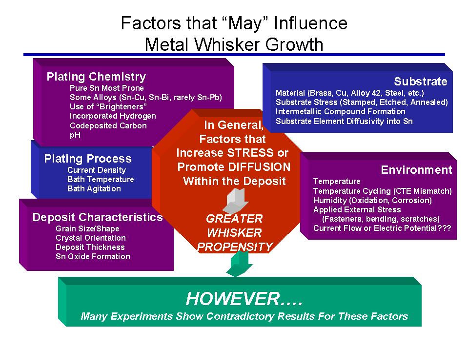
The mechanisms by which tin whiskers grow have been studied for many years. A single accepted explanation of the mechanisms has NOT been established. Some theories suggest that tin whiskers may grow in response to a mechanism of stress relief (especially "compressive" stress) within the tin plating. Other theories contend that growth may be attributable to recrystallization and abnormal grain growth processes affecting the tin grain structure (which may or may not be affected by residual stress in the tin plated film).
In the case of stress within the tin plating, there are some commonly accepted factors that can impart additional residual stress:
-
Residual stresses within the tin plating caused by factors such as the plating chemistry and process. Electroplated finishes (especially "bright" finishes) appear to be most susceptible to whisker formation reportedly because bright tin plating processes can introduce greater residual stresses than other plating processes.
-
Intermetallic Formation: The diffusion of the substrate material into the tin plating (or vice versa) can lead to formation of intermetallic compounds (such as Cu6Sn5 for a Sn over Cu system) that alter the lattice spacing in the tin plating. The change in lattice spacing may impart stresses to the tin plating that may be relieved through the formation of tin whiskers.
-
Externally Applied Compressive Stresses such as those introduced by torquing of a nut or a screw
-
Bending or Stretching of the surface after plating (such as during lead-formation prior to mounting of an electronic component)
-
Scratches or nicks in the plating and/or the substrate material introduced by handling, probing, etc.
-
Coefficient of Thermal Expansion Mismatches between the plating material and substrate
![]()
What are the Risks/Failure Mechanisms Associated with Tin Whiskers?
Tin whiskers pose a serious reliability risk to electronic assemblies. Several instances have been reported where tin whiskers have caused system failures in both earth and space-based applications. To date, there are reports of at least three tin whisker induced short circuits that resulted in complete failure of on-orbit commercial satellites.
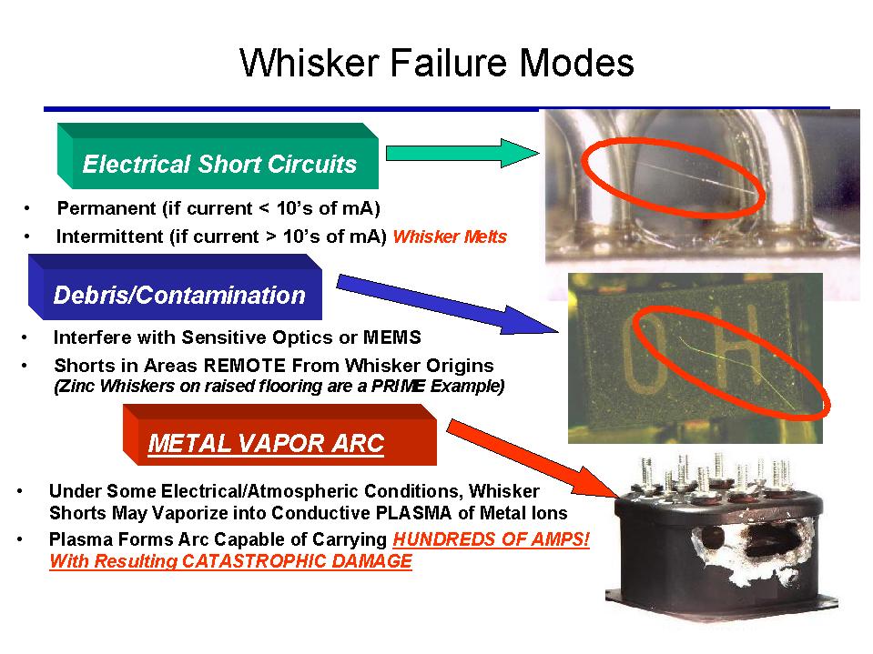
The general risks fall into four categories:
- Stable short circuits in low voltage, high impedance circuits.
In such circuits there may be insufficient current available to fuse the whisker open and a stable short circuit results. Depending on a variety of factors including the diameter and length of the whisker, it can take more than 50 milliamps (mA) to fuse open a tin whisker.
At atmospheric pressure, if the available current exceeds the fusing current of the whisker, the circuit may only experience a transient glitch as the whisker fuses open.
If a tin whisker initiates a short in an application environment possessing high levels of current and voltage, then a VERY DESTRUCTIVE phenomenon known as a Metal Vapor Arc can occur. The ambient pressure, temperature and the presence of arc suppressing materials also affect metal vapor arc formation. In a metal vapor arc, the solid metal whisker is vaporized into a plasma of HIGHLY CONDUCTIVE metal ions (more conductive than the solid whisker itself). This plasma can form an ARC capable of carrying HUNDREDS OF AMPERES. Such arcs can be sustained for long duration (several seconds) until interrupted by circuit protection devices (e.g., fuses, circuit breakers) or until other arc extinguishing processes occur. This kind of arcing is happening in the metal vapor. When an arc quenching agent (e.g., air) is present, more power must be installed into the event to replace power lost to the non-interesting processes happening in the quenching agent. Therefore, as air pressure is reduced, less power is required to initiate and sustain a whisker-induced metal vapor arc. For example, past experiments** have demonstrated that at atmospheric pressures of about 150 torr, a tin whisker could initiate a sustained metal vapor arc where the supply voltage was approximately 13 Volts (or greater) and supply current was 15 Amps (or greater). Tin (or other materials) from the adjacent surfaces can help to sustain the arc until the available material is consumed or the supply current is interrupted. Metal vapor arcs in vacuum are reported to have occurred on at least three commercial satellites resulting in blown fuses that rendered the spacecraft non-operational.
** J.H. Richardson, and B.R. Lasley, "Tin Whisker Initiated Vacuum Metal Arcing in Spacecraft Electronics," 1992 Government Microcircuit Applications Conference, Vol. XVIII, pp. 119 - 122, November 10 - 12, 1992.
Whiskers or parts of whiskers may break loose and bridge isolated conductors or interfere with optical surfaces
![]()
Why the Recent Attention to Tin Whiskers?
The current worldwide initiative to reduce the use of potentially hazardous materials such as lead (Pb) is driving the electronics industry to consider alternatives to the widely used tin-lead alloys used for plating. For example, the European Union has enacted legislation known as the Restriction of certain Hazardous Substances (RoHS) and Waste Electrical and Electronic Equipment (WEEE) Directives which have set June 2006 as deadlines for electronic equipment suppliers to eliminate most uses of Pb from their products. It is widely believed (though reasons remain somewhat of a mystery) that Pb when alloyed with tin imparts whisker-inhibiting attributes to the final finish.
With respect to factors such as solderability, ease of manufacture and compatibility with existing assembly methods, pure tin plating is seen by the industry as a potentially simple and cost effective alternative. In fact, many manufacturers have been offering pure tin plated components as a standard commercial (and in some cases high reliability) product for years while others are exploring pure tin alternatives for the very first time. Many electronics manufacturers have never heard of the phenomenon of tin whiskers and therefore, may not consider the risks of tin whisker growth during the validation of new plating systems.
Continuing reports of tin whisker-induced failures coupled with the lack of an industry accepted understanding of tin whisker growth factors and/or test methods to identify whisker-prone products has made a blanket acceptance of pure tin plating a risky proposition for high reliability systems. Still, organizations such as NASA and the DoD may soon be faced with few options other than pure tin plating since the desires of the commercial market for environmentally friendly components carry far more weight than the infinitesimally small market share of the high reliability user.
![]()
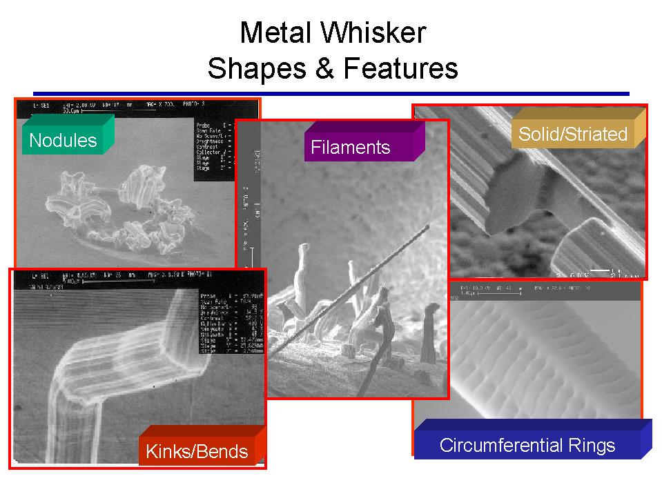
What are the Commonly Reported Characteristics of Tin Whiskers?
The vast disparity in the observations reported by different experimenters is evidence of the complications associated with understanding and controlling tin whiskers. The following list is intended to provide a very basic overview of some of the observed characteristics of tin whiskers.
-
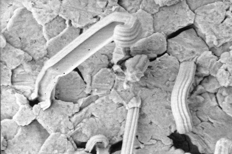
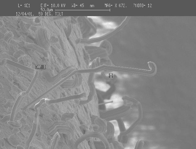
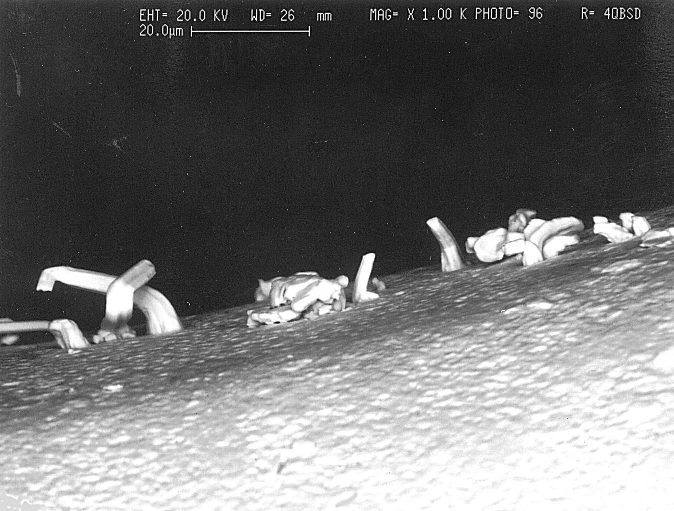
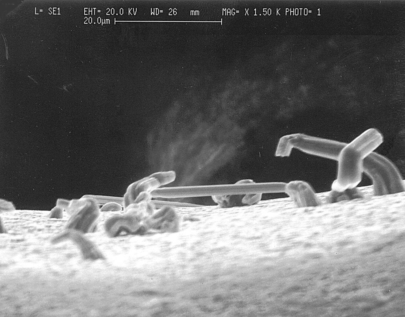
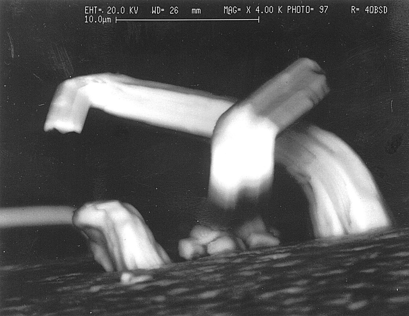
Shapes: Whiskers may be straight, kinked, hooked or forked. Their outer surfaces are often grooved. Some growths may form as nodules or pyramidal structures.
-
Incubation (Dormancy) Period: Experimenters report the incubation period may range from days to years. This attribute of whisker growth is particularly concerning because meaningful experiments to determine the propensity for a particular process to form whiskers may need to span very long periods of time.
-
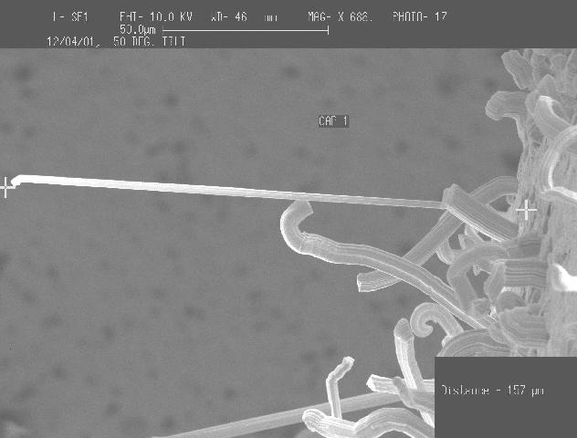
Growth Rate: Growth rates from 0.03 to 9 mm/yr have been reported. Growth is highly variable and is likely to be determined by a complex relationship of factors including plating chemistry, plating thickness, substrate materials, grain structure and environmental storage conditions.
-
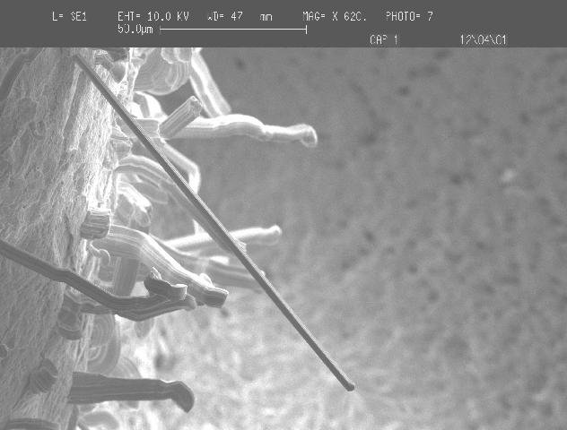
Whisker Length: Whiskers as long as a few millimeters are not uncommon with some experimenters observing whiskers as long as10 mm (400 mils) in length.
-
Whisker Diameter: Typical diameters are a few microns with some reports as large as 10 um
-
Environmental Factors: There is a great deal of contradictory information regarding environmental factors that might affect whisker formation. Several organizations are attempting to devise accelerated test methods to determine a particular plating process's propensity to form tin whiskers. However, to date, there are no accepted test methods for evaluating whisker propensity. Indeed, much of the experimental data compiled to date has produced somewhat contradictory findings regarding which factors accelerate (or retard) whisker growth.
|
Temperature: Some experimenters report that ambient temperatures of approximately 50°C are optimal for whisker formation, while others observe that room temperatures (22°C to 25°C) grow whiskers faster. Reportedly, whisker growth ceases at temperatures above 150°C | |
|
Pressure: Whiskers will grow in vacuum as well as earth based atmospheric pressure. | |
|
Moisture: Some observe that whiskers form more readily in high humidity (85% RH) whereas others report moisture is not a contributing factor | |
|
Thermal Cycling: Some experimenters report that thermal cycling increases the growth rate of whiskers, but others report no effect due to thermal cycling. | |
|
Electric Field: Whiskers grow spontaneously without requiring an applied electric field to encourage their growth. Some recent observations of tin whisker induced field problems in the commercial sector seem to suggest that an electric field could stimulate whisker growth, but more analysis is required to confirm these effects (if any). GSFC has demonstrated that whiskers can bend due to the forces of electrostatic attraction thus increasing the likelihood of tin whisker shorts (ref. to GSFC experiment #4). |
Whisker Prone Processes: There is tremendous debate in the industry regarding which plating processes are prone to whisker formation. Most of the literature agrees that "pure tin" electroplated surfaces (especially those that employ brighteners in the plating process) are the most susceptible to whisker formation. There are also reports that tin-lead plating can also grow whiskers; however, such whiskers are generally reported to be less than 50um long.
![]()
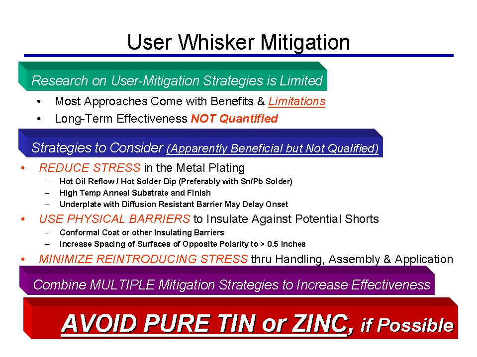
Suggestions for Reducing Risk of Tin Whisker Induced Failures:
The uncertainties associated with tin whisker growth make it extremely difficult to predict if/when tin whiskers may appear. The following list provides some suggestions for reducing the risk of tin whisker induced failures.
-
Avoid the use of PURE TIN plated components if possible. Utilization of procurement specifications that have clear restrictions against the use of pure tin plating is highly recommended. Most (but not all) of the commonly used military specifications currently have prohibitions against pure tin plating. Studies have shown that alloying tin with a second metal reduces the propensity for whisker growth. Alloys of tin and lead are generally considered to be acceptable where the alloy contains a minimum of 3% lead by weight. Although some experimenters have reported whisker growth from tin-lead alloys, such whiskers have also been reported to be dramatically smaller than those from pure tin plated surfaces and are believed to sufficiently small so as not to pose a significant risk for the geometries of today's microelectronics.
-
Post Procurement It can be dangerous to rely on the part manufacturer's certification that pure tin plating was not used in the production of the product supplied. NASA GSFC is aware of several instances where the procurement specification required "No Pure Tin", but the product supplied was later determined to be pure tin. In some of these instances, tin whisker growths were also discovered. Users are advised to analyze the plating composition of the products received as an independent verification.
When simple avoidance of pure tin plating is not a viable option (such as in cases where its use is discovered late in system integration/test), then the following approaches may also be considered to reduce risk.
-
Solder Dip the plated surfaces sufficiently using a tin-lead solder to completely reflow and alloy the tin plating. Obviously, special precautions are required to prevent thermal shock induced damage, to prevent loss of hermeticity and to avoid thermal degradation. This approach may have limited success since it may be difficult to ensure that the entire surface is properly reflowed. See the April 2004 Photo of the Month for one example of the limitations associated with this particular mitigation strategy.
-
Replate the whisker prone areas. Some manufacturers may be willing to strip the pure tin plate from finished products and re-plate using a suitable alternate plating material such as tin/lead or Nickel. Caution is advised if considering use of an external plated finish (e.g., Sn-Pb or Cu) on top of an existing pure tin deposit. There is some evidence that whiskers may still form from the pure tin layer and protrude through the thin external deposit.
-
Conformal Coat or foam encapsulation over the whisker prone surface appears to be beneficial but the limitations are not completely understood. NASA GSFC experiments suggest that use of Uralane 5750 conformal can provide some benefit by reducing the growth rate, but tin whiskers can grow through conformal coating and once exposed can then short to other tin whiskers or other exposed surfaces. See also a technical paper (~11 Mbytes) and presentation (~19 Mbytes) by Dr. Tom Woodrow (Boeing) from 2005 in which he evaluated 6 different conformal coat materials for purposes of inhibiting whisker formation and subsequent shorting hazards.
It has also been demonstrated experimentally that conformal coating can restrict the availability of tin sufficiently to minimize the risk of plasma formation. However, such factors as the minimum thickness of coating necessary to prevent whisker growth or plasma formation have not been determined. Similarly, it has been shown that foam can prevent sustained arcing but the effects of foam type, foam density, pore size etc. have not been evaluated. Additional studies and evaluations are underway to try to answer the critical open questions in order to provide more detailed suggestions in the future. -
Evaluate Application Specific Risks. A variety of application specific considerations may be used to assess the risk of whisker induced failures and assist in making "use as-is" or "repair/replace" decisions. These factors include circuit geometries that are sufficiently large to preclude the risk of a tin whisker short, mission criticality, mission duration, collateral risk of rework, schedule and cost. To assist in evaluating application specific risks, David Pinsky (Raytheon) has developed a tin whisker risk assessment algorithm which can be reviewed (note: reference to this algorithm herein does not imply endorsement by NASA).
In 2002, Dr. Mike Osterman (CALCE Center at the University of Maryland) published a white paper outlining pros and cons of assorted strategies for mitigating risks associated with tin whiskers.
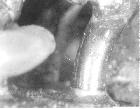
UPDATED Nov. 19, 2002 The Relays shown below are plated with pure tin. This plating exists over the entire case, header and the hook terminals that will normally have stranded wire soldered to the end of the hooks. Whisker shorts can occur due to whiskers growing from either the case, header or the terminals. Even when terminals have wire soldered to the hooks, whiskers have been observed growing from the base of the terminals near the glass to metal seals.
Photos Courtesy of NASA GSFC
Photos Courtesy of Space Systems Loral
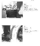
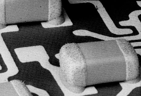
Ceramic Chip Capacitors These commercial (size 0805) ceramic chip capacitors have pure tin plated terminations over a nickel barrier layer. The user mounted them using conductive epoxy (i.e, not reflow soldered) and after thermal cycle testing discovered the tin whisker farm. After thermal cycling max. whisker lengths of 100 microns were observed. HOWEVER, after additional room ambient storage (6 - 8 months) the whiskers continued to grow with some in excess of 200 microns (max. length ~240 microns). It has NOT been experimentally shown whether soldering these parts to the board would have eliminated the whisker concern through either reflow of the terminations or mixing of "most" of the termination surface with the mounting solder (typically tin/lead based). See NASA GSFC Experiment #5 for more info. Photos Courtesy of I. Hernefjord & NASA Goddard
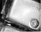
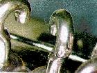
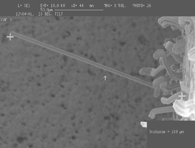
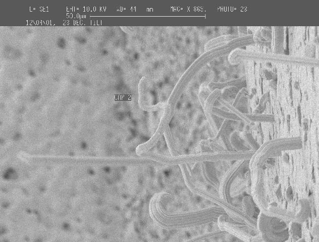
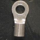
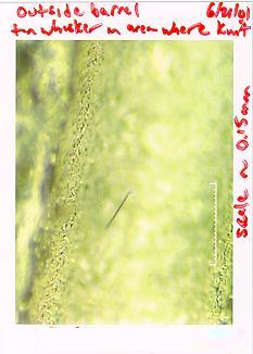
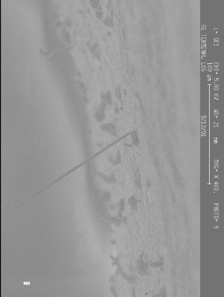
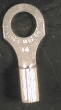
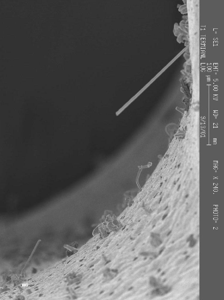
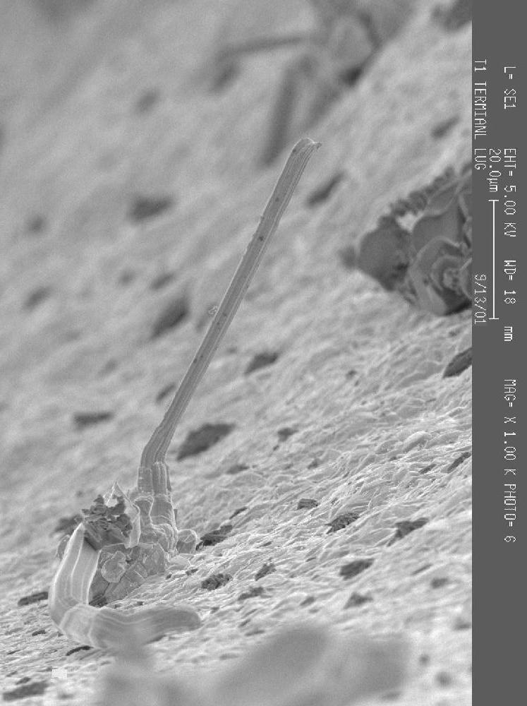
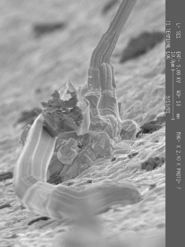
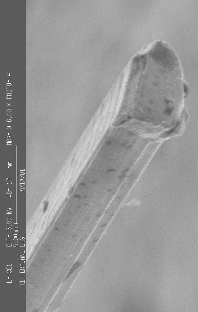
The terminal rings shown below are plated with pure tin. These terminal rings are commonly used in "crimp" type applications where a stranded wire is inserted into the barrel and crimped in place. The ring terminal portion is most often mounted using a nut and bolt to adhere the ring to a conductive surface such as a chassis. These photos are of "unused/loose piece" terminal rings taken straight from the manufacturer's shipping containers. Almost all of the whiskers photographed were found "inside" the crimp barrel of these parts. A few very short whiskers were also observed on the external part of the barrel in the "seam". Photos Courtesy of NASA GSFC
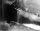
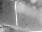
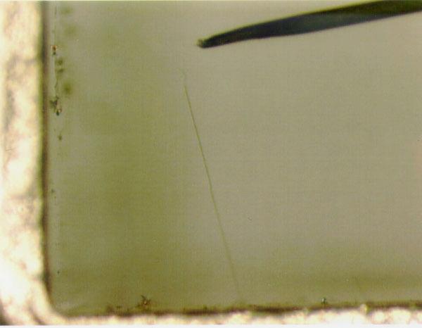
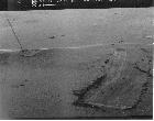
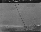
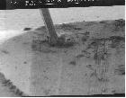
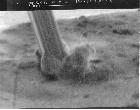
The photo below is of the package lid of a hybrid microcircuit. The lid was plated with pure tin. This whisker was found growing on the on the surface of the lid that was facing INSIDE the of the device. Other whiskers were also found on the lids with some as long as 2 mm.
Photos Courtesy of NASA Goddard Space Flight Center
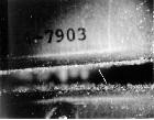
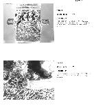
Tin Whiskers growing on a MATTE tin-plated copper leadframe commonly used in the manufacture of 28 pin small outline integrated circuit
(SOIC) leadframe after 3 years of ambient storage.
Photos Courtesy of Peter Bush (State University New York at Buffalo)
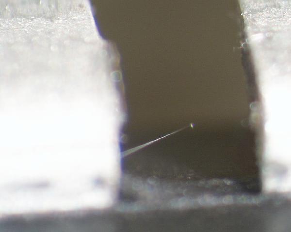
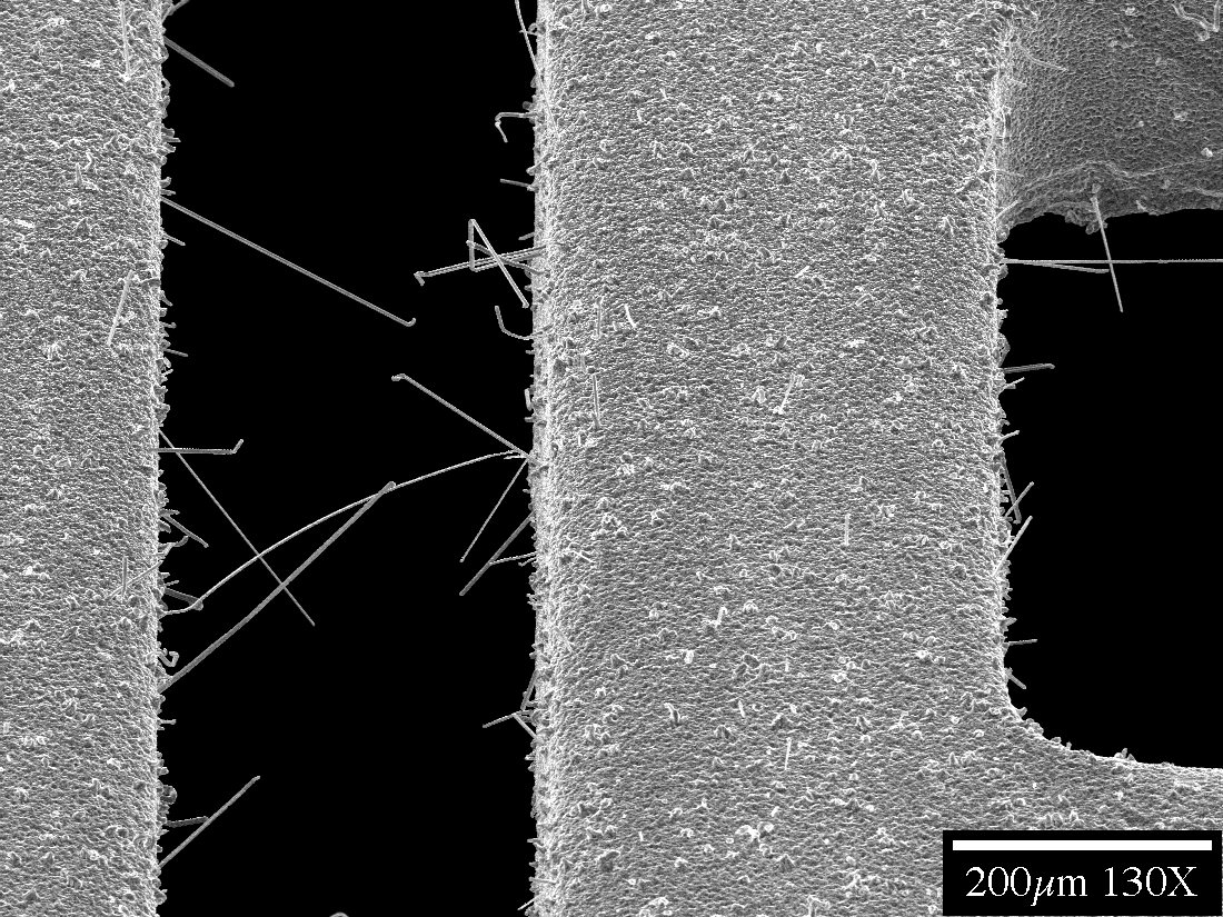
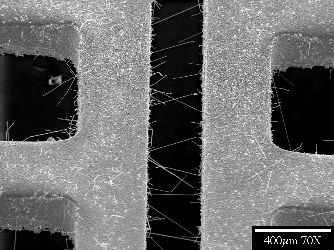
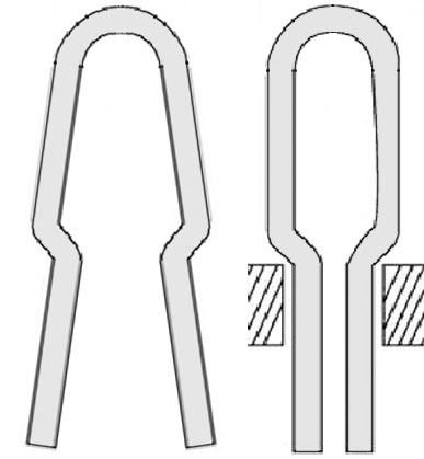
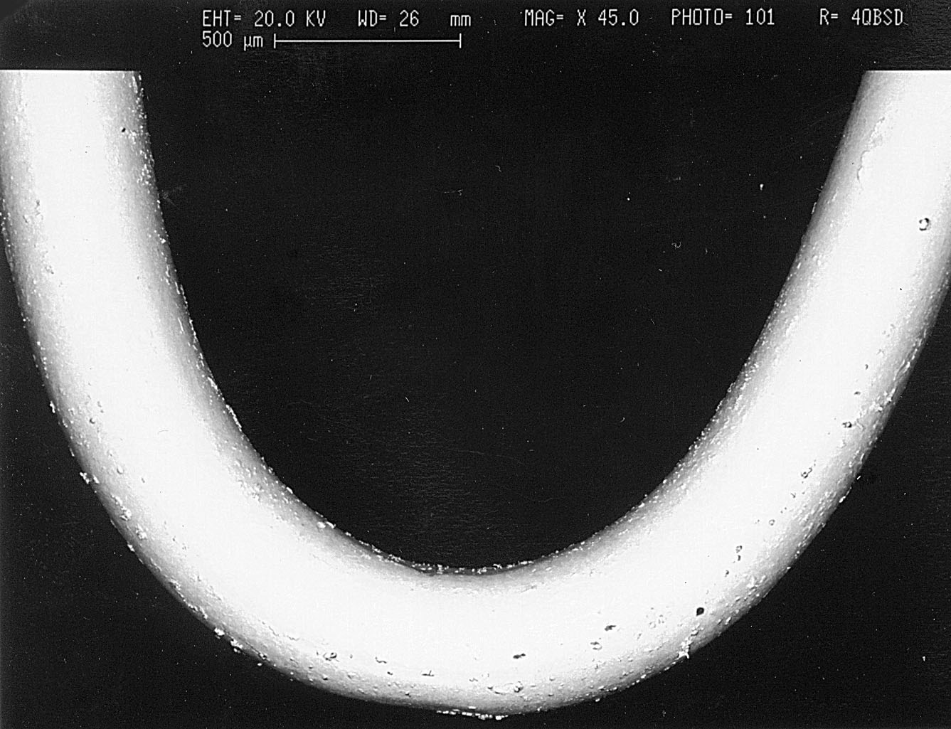
The test points shown here are "bright" tin-plated phosphor bronze loops. They are commonly installed on PC Boards as access points for attaching test leads/probes to monitor signals and voltages during board level testing.
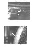
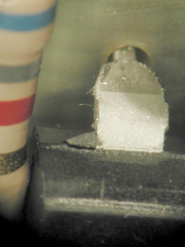
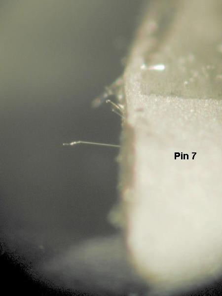
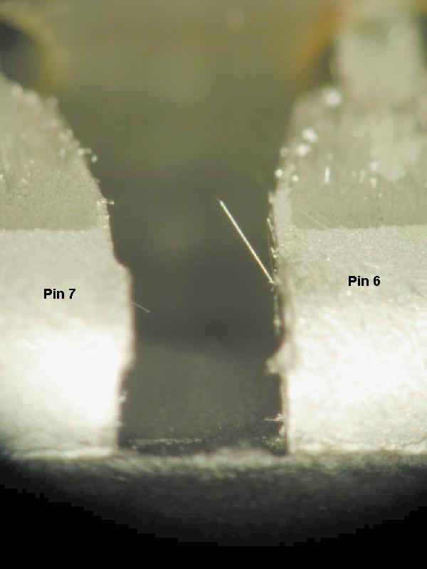
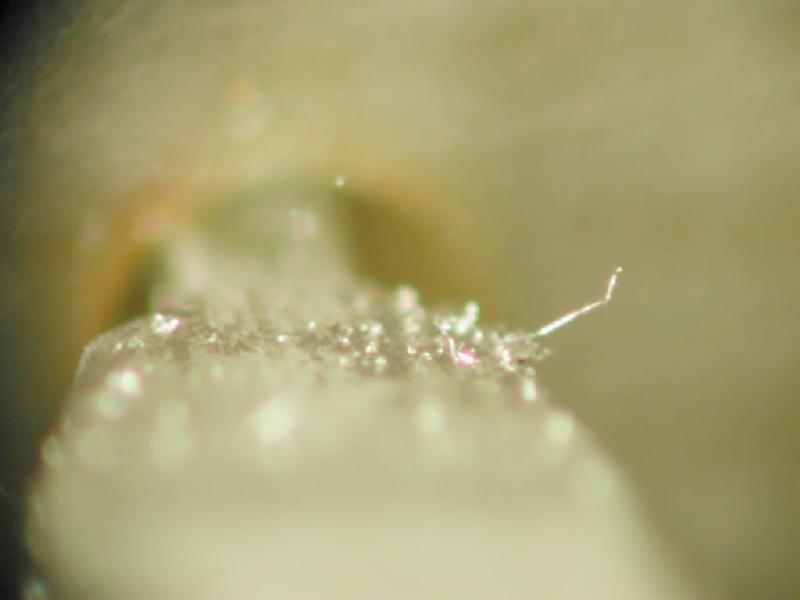
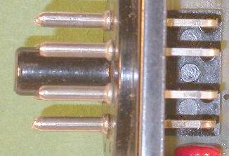
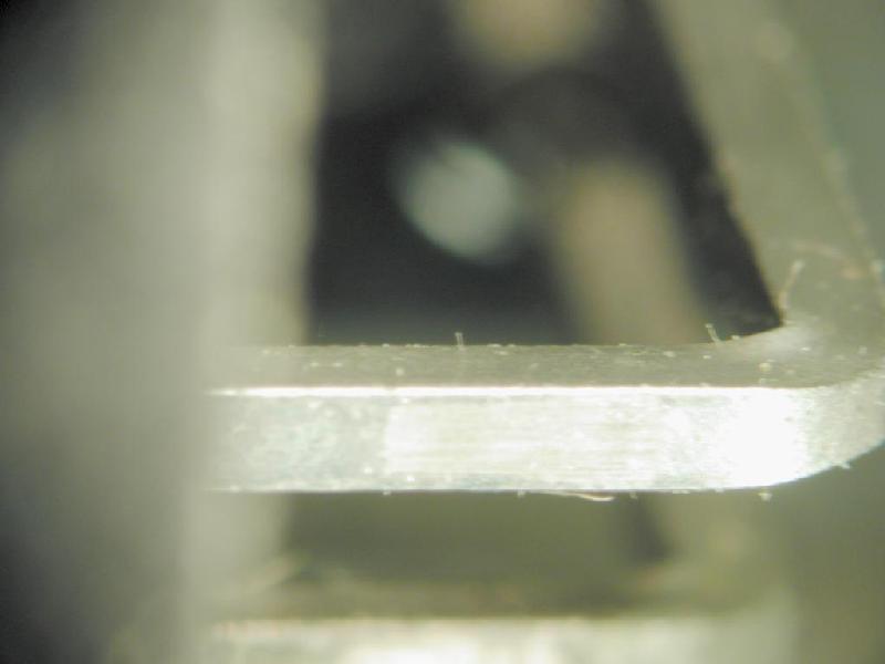
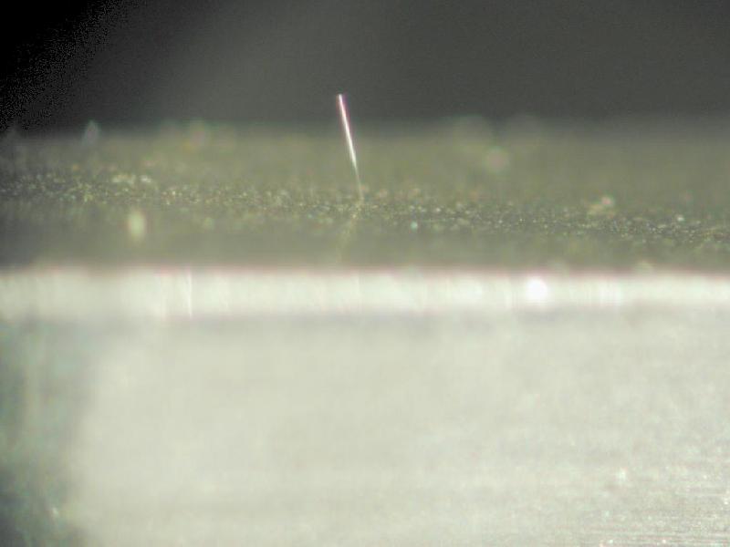
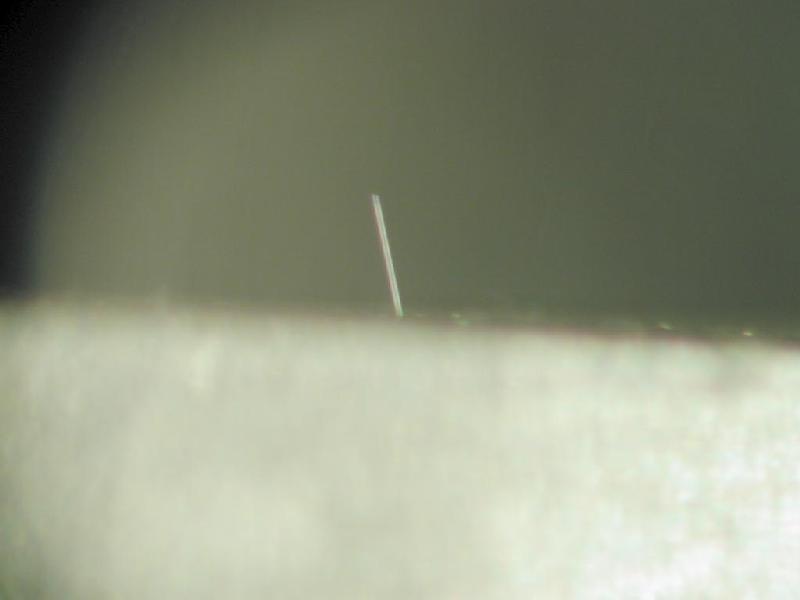
The connector below is an octal type connector with circular cross-section pins on the plug-in side (left side of first image below) and rectangular cross-section pins on the right angle mount solderable contacts (right side of first image). The pins are pure tin-plated. Tin whiskers were found on the rectangular cross section pins while performing an inspection of a module reported to have failed in a commercial electric power utility application due to tin whisker shorts originating from a microcircuit also used in this assembly.
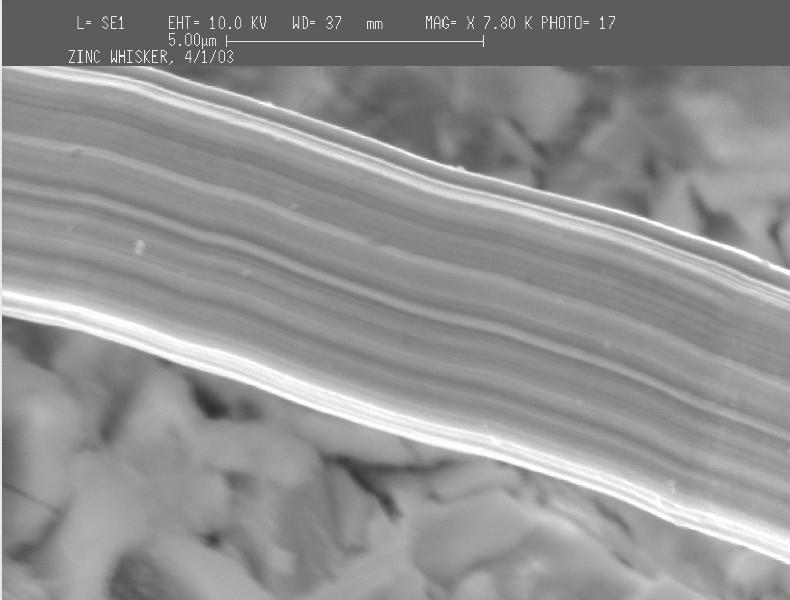
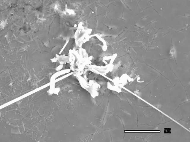
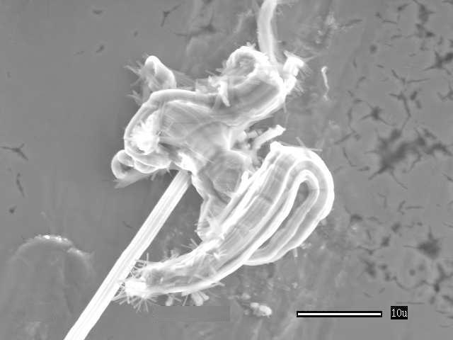
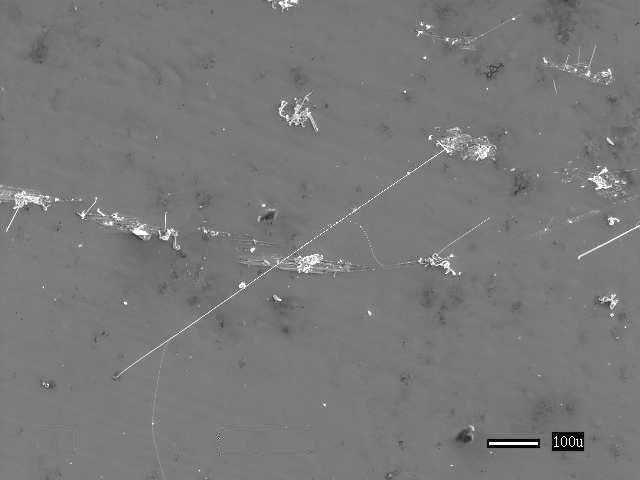
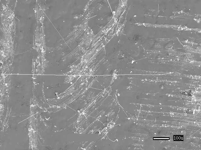
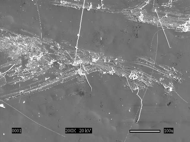
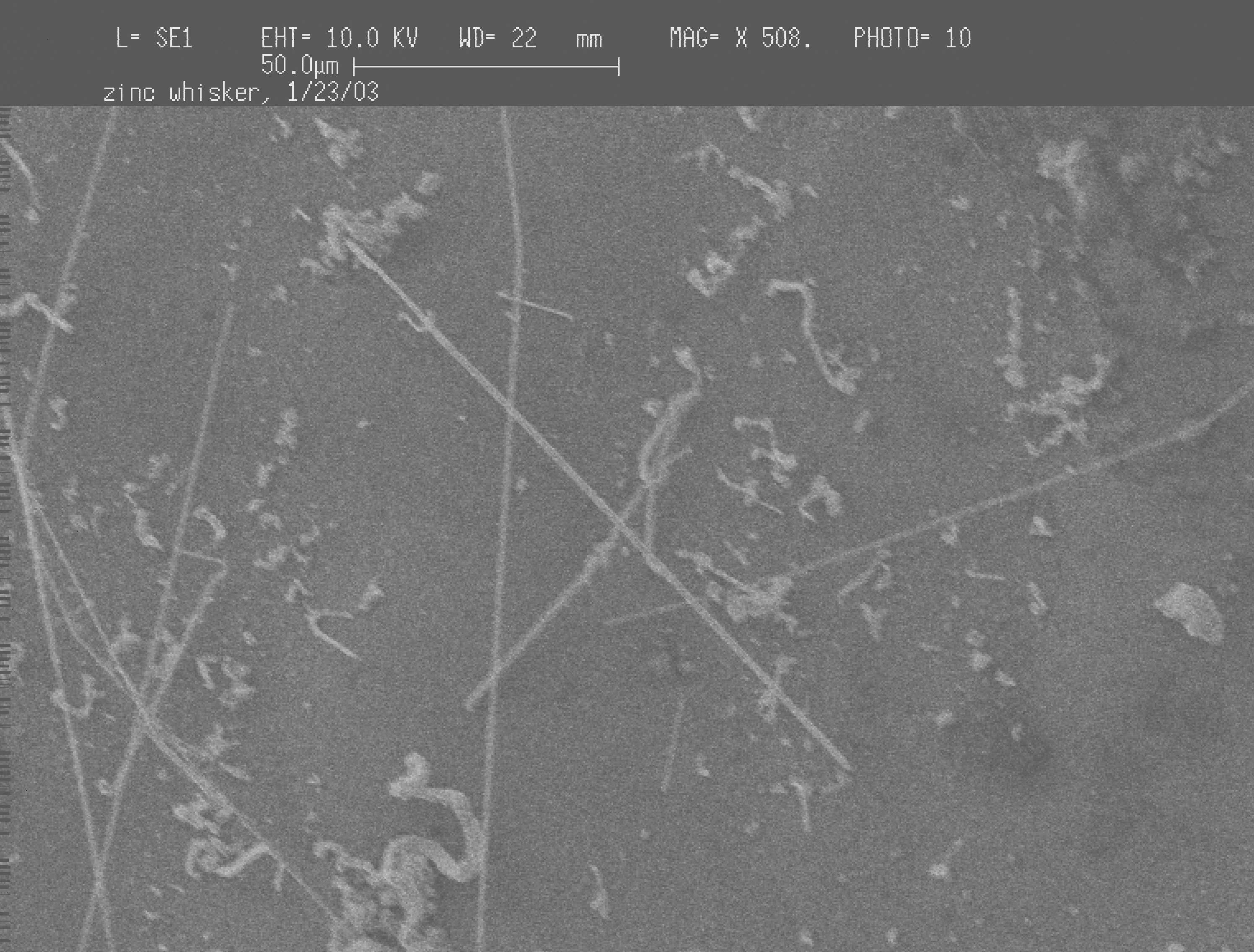
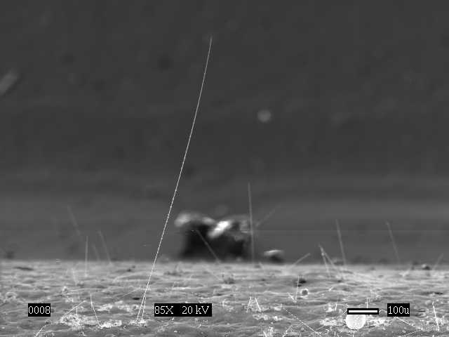
Raised Floor Tiles and Support Structures with ZINC Whiskers The whiskers below are ZINC WHISKERS. They were found growing on the zinc-coated steel underside of raised floor tiles. In these examples the floor tiles were part of a computer room in which zinc whisker debris was shed from the floor tiles especially during maintenance activities within the data center . The conductive whisker debris was distributed around the room via the air cooling system. Ultimately, some whisker debris was drawn inside of the electronic systems (e.g., servers, routers, disk arrays) operating in the data center resulting in catastrophic and/or intermittent short circuit failures. ADDITIONAL GALLERY of Zinc Whisker Photos on Raised Floor Structures
Photos Courtesy of NASA Goddard Space Flight Center
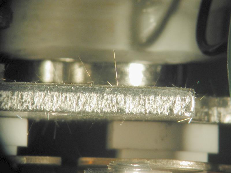
Zinc-Plated Steel Bus Rail (Documented in 2001) The images below depict ZINC whiskers found growing on a zinc electroplated steel bus rail. This rail also has a yellow chromate finish which obviously did not inhibit whisker formation. Whiskers up to several millimeters long were observed. The user of this bus rail determined the zinc whiskers were the root cause of catastrophic electrical shorting failure during a thermal vacuum test. ADDITIONAL GALLERY of Zinc Whisker Photos on this Bus Rail
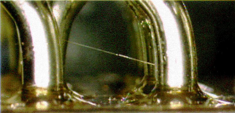
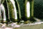
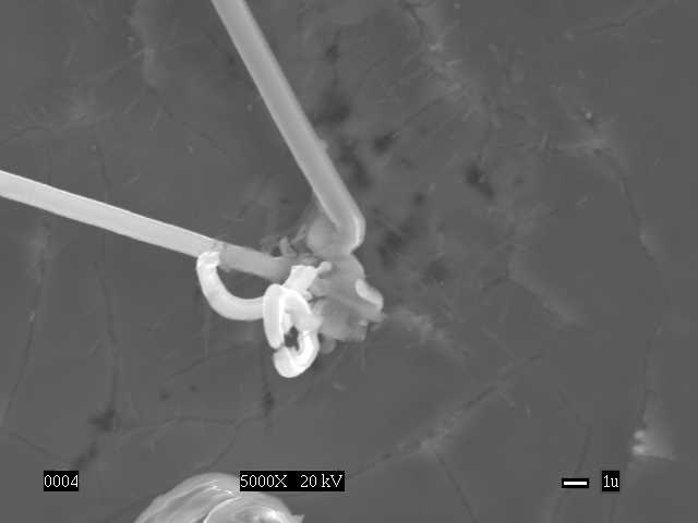
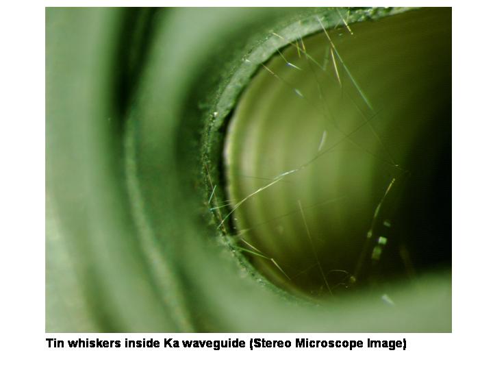
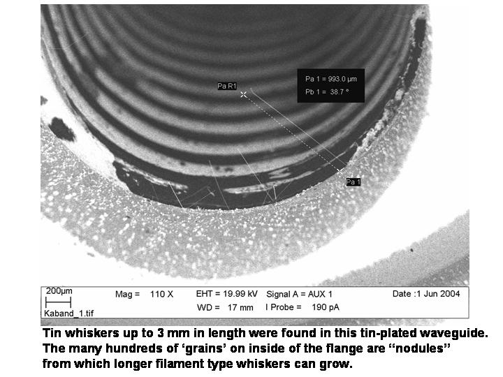
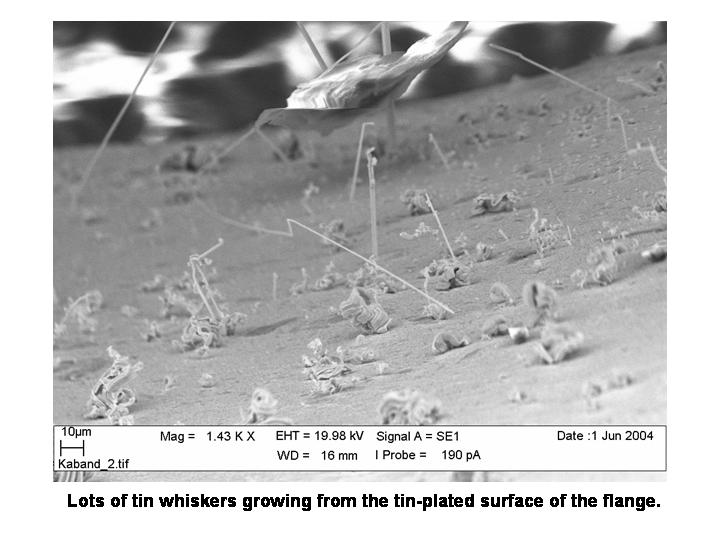
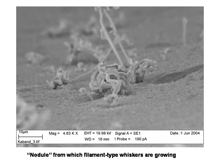
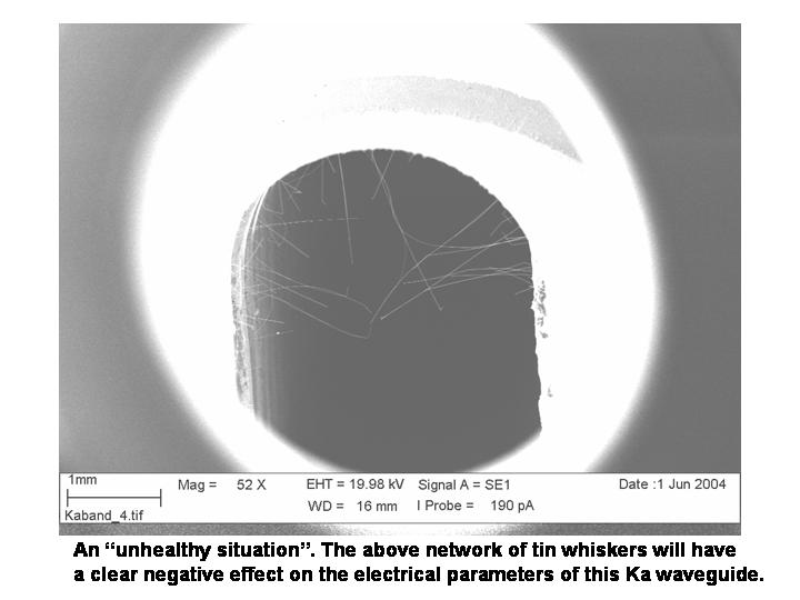
Tin-Plated Flange of a Waveguide (Documented in 2004) The images below depict tin whiskers found growing from the tin-plated flange of a Ka band waveguide. The high density of whiskers, some approaching 5-mm long, were found within several weeks of receipt of product by the waveguide user. In the end application whiskers of this size and density produced signal reflections and losses that affected the electrical performance of the waveguide. ADDITIONAL Tin Whisker Images of this Waveguide
|


Raised Floor Tiles with ZINC Whiskers
The whiskers below are ZINC WHISKERS. They were found growing on the zinc-coated steel underside of raised floor tiles. In these examples the floor tiles were part of a computer room in which zinc whisker debris was shed from the floor tiles especially during maintenance activities within the data center . The conductive whisker debris was distributed around the room via the air cooling system. Ultimately, some whisker debris was drawn inside of the electronic systems (e.g., servers, routers, disk arrays) operating in the data center resulting in catastrophic and/or intermittent short circuit failures.
See the presentation: "Zinc Whisker Awareness: Could Zinc Whiskers Be Impacting Your Electronics?" for More about Zinc Whisker


